Questions and Answers
Is the bow bumper of a boat which meets the required 10 mm only at deck level and thinning towards the water line in accordance with IOM Class Rules?
Question details:
Is the bow bumper of a boat which meets the required 10 mm only at deck level and thinning towards the water line in accordance with IOM Class Rules?
Reference to the old interpretation issued before the year 2017
Interpretation 2004-IOM-3 on IOM Class Rules – edition 2003
Answers:
IOM class rule D.2.2(c)) is dealing with “the forward 10 mm of the hull”. Relevant ERS 2017-2020 rules are H.3.1 and H.3.4. According to them, longitudinal measurements such as “forward 10 mm of the hull” shall be taken parallel to the horizontal hull axis. Therefore the hull forward of a vertical plane 10 mm aft of the foremost point of the hull and at 90 deg. to the hull centreplane has to comply with IOM class rule D.2.2(c).
So, the bumper in diagram “A” is NOT legal, because part of the forward 10 mm of the hull is not made of elastomer. The bumpers of “B” and “C” are permitted, since all of the forward 10 mm of the hull is a bumper, even though in “B” this bumper thins out to 0 before it reaches the waterline.
What range of elastomers are permitted for bumpers?
Questions related to the various chainplates positions on the hull
Question details:
With the emergence of the new high prismatic narrow hulls with chines, the decks are becoming much narrower than traditional IOM designs. With a narrow deck, the chainplate position moves inboard and the shroud base gets narrower. I have attached pictures of a narrow IOM (see below) with rounded sides where the chainplate eye has been placed proud on the center of the topsides to widen the shroud base. See diagram F.
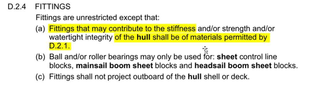
The question is does this contravene IOM class rule D.2.4(c) Fittings shall not project outboard of the hull shell or deck.
This question raises the issue of the location of the sheer and where the deck ends and the topsides of the hull begin. The chainplate eye can project above the deck, but cannot project outboard of the hull shell. So how do we interpret the class rule for the diagram examples B, C, D, E and F?
It also asks the question about the hull shell – is the class rule use of SHELL, referring to the plane of the hull in the area of the chainplate eye, or is it referring to max beam?
In case B, the sheer is a small radius curve and the chainplate eye extends outboard of the hull lines and max beam.
In case C, the sheer is a large radius, and the chainplate eye lies inside the max beam. There may be some questions as to where to locate the projection lines.
In case D, the hull bottom is round and the chine extends from a vertical tangential extension at max beam. The chainplate eye is outboard of the chine, but inside the max beam.
In case E, the hull bottom is a flat section and the chine extends from a wide angle tangential extension at max beam. The chainplate eye is outboard of the chine, but inside max beam.
In case F, the hull is an oval with no discernible sheerline or chines where the chainplate eye is attached. This matches the picture of the IOM (below).


Reference to the old interpretation issued before the year 2017
Interpretation 2013-IOM-1 on IOM Class Rules – edition 2013
Answers:
Relevant IOM Class Rule:
D.2.4(c) Fittings shall not project outboard of the hull shell or deck.
Relevant ERS 2017-2020 rules:
D.1.1 Hull – The hull shell including any transom, the deck including any superstructure, the internal structure including any cockpit, the fittings associated with these parts and any corrector weights.
H.3.1 – For a boat, unless otherwise specified, words such as “fore”, “aft”, “above”, “below”, “height”, “depth”, “length”, “beam”, “freeboard”, “inboard” and “outboard” shall be taken to refer to the boat in measurement trim. All measurements denoted by these, or similar words, shall be taken parallel to one of the three major axes.
Shrouds attachment points (chainplate eyes) as shown on the sketch and marked with A, C, D, E and F and shown on the photo are not projecting outboard of the hull shell and they are permitted by the IOM Class Rules.
Shrouds attachment points (chainplate eyes) as shown on the sketch and marked with B are projecting outboard of the hull shell and therefore not permitted by the IOM Class Rules.
Is it permitted to use fillers and gel coats containing micro balloons?
Questions related to the various materials used to build the IOM hull related to the IOM Class Rule D.2.1(a).
Is accidentally moulded small bits are permitted in a moulded hull?
Is it permitted to use standard servo casings?
Is sticky cloth deck patch material permitted?
Is it permitted to use a “Texalium” in the IOM moulding hulls?
Are “pellettised” thermoplastics with unknown additives permitted?
Is it permitted to fix the corrector weight(s) inside the hull by using hook and loop fasteners (Velcro)?
Deck shapes / number / extensions?
Having in mind closed rules nature of the IOM Class Rules and that deck is not an ERS defined term is there any restriction on placing vertical part on the IOM deck (like one on the photo?

Answer:
Relevant IOM Class Rule:
- 2.2. Construction
- 2 Transverse hull hollows
Discussion:
– For the purpose of this Q&A the vertical item on the deck is called “air appendage”.
– “Air appendage” does not meet the ERS definition of hull appendage because it is not partly or wholly below the sheerline.
– If such air appendage” is permanently fixed to the deck it should be treated as a “complex shaped deck”.
Decision:
Deck is not ERS defined term and shape of the deck is not restricted/defined in the IOM Class Rules.
There is no restriction on the shape of the deck in the IOM Class rules except those given in IOM Class Rule I.2.
Use of “air appendages” fixed to the deck as shown on the photo in question is permitted by the current IOM Class Rules 2022.
Is an interpretation and consequent Class Rule change needed?
No.
Note: In order to prohibit such “air appendages” class rule amendment is needed”.
IOM ICA Technical Subcommittee
20 March 2024
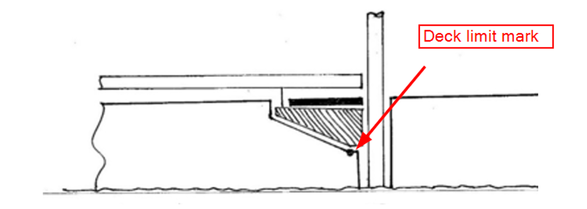
Vertical placement of deck limit mark.
Received from designer Graham Bantock.
Relevant IOM Class Rules:
D.1.5 DECK LIMIT MARK
The deck limit mark shall be displayed on the centre plane of the hull near to the mast position. It shall be a minimum of 5 mm in diameter.
F.2.4 CONSTRUCTION
(a) Fittings and/or control lines may be combined provided their function is not extended beyond what is permitted.
(b) The position of parts, and the length and tension of rigging, may be adjustable unless otherwise restricted.
(c) Ball and/or roller bearings may be used for: kicking strap fitting; gooseneck; mainsail boom sheet blocks; headsail boom sheet blocks; headsail boom swivel.
(d) Where the mast kicking strap fitting and/or gooseneck:
(1) are exposed,
(2) are not of circular cross section, and
(3) rotate,
they shall not exceed 20 mm in any cross section perpendicular to the axis of rotation.
Questions and Answers
Questions are related to the diagrams and explanations shown below.
Item 4
Question: Is it reasonable that the mast deck limit mark can be placed at some distance down the mast trunking? Is this arrangement permitted?
Answer: Yes. Deck limit mark of minimum 5 mm in diameter shall be positioned on the centre plan of the hull near the mast position as defined in the IOM Class Rule D.1.5. Deck limit mark should be visible and should be possible to take measurement from that point (centre of deck limit mark).
Item 5
Question: Whereas there have been aft extensions of the foredeck past the mast position (and these are acknowledged as permitted by the Q&A), does the same logic apply to a plate that more fully closes the well?
Is it correct to accept that the mast deck limit mark is placed underneath the plate that more fully closes the well?
Answer: Deck limit mark may be placed on the deck underneath the kicking strap/gooseneck mast fitting regardless of the type/execution of the kicking strap/gooseneck mast fitting.
Item 6
Question: Whereas there have been aft extensions of the foredeck past the mast position (and these are acknowledged as permitted by the Q&A), does the same logic apply to a plate that more fully closes the well?
The mast kicking strap fitting in this case is normal. CR F2.4 (d) is complied with.
Is it permitted to place the mast deck limit mark underneath the plate that more fully closes the well?
Answer: Yes
Diagrams of centre plane cross sections in region of mast – brief descriptions
In all diagrams the mast deck limit mark is located where indicated by the dot.
In all cases the kicking strap itself is a conventional thin wire or line.
1 The typical arrangement in the early days of the class. A flat deck, mast trunking, mast deck limit mark on the flat deck adjacent to the mast.
2 The arrangement developed by Craig Smith around the mid1990s where the foredeck is raised and a ‘cockpit’ is formed aft of the partial bulkhead just ahead of the mast. The mast deck limit mark is on the floor of the cockpit adjacent to the mast.
3 The arrangement that evolved in the late 1990s where the foredeck is raised and a ‘well’ is formed around the mast. The mast deck limit mark is on the floor of the well adjacent to the mast.
4 As arrangement 3 but where the size of the well is progressively reduced to a minimal size. The mast deck limit mark is on the floor of the well adjacent to the mast.
5 As arrangement 3 but where the well is partially closed in by a plate (shown in solid) attached to and flush with the surrounding deck. The kicking strap attachment on the mast is a triangular plate in excess of 20 mm in vertical and horizontal dimensions (shown hatched). The kicking strap is near vertical connecting the main boom to the mast kicking strap attachment. The mast deck limit mark is on the floor of the well adjacent to the mast.
6 As arrangement 3 but where the well is partially closed in by a plate (shown in solid) attached to and flush with the surrounding deck. The kicking strap is normal. The mast deck limit mark is on the floor of the well adjacent to the mast.

29 January 2025
Is the mast kicking strap fitting and/or gooseneck on following sketch “exposed” according to the IOM Class Rule F2.4 (d) (1)
Exposed mast kicking strap fitting and/or gooseneck.
Received from designer Graham Bantock.
Question:
Is the mast kicking strap fitting and/or gooseneck on following sketch “exposed” according to the IOM Class Rule F2.4 (d) (1)

Answer:
Deck limit mark is positioned on the deck as shown on the sketch. It is below the mast kicking strap fitting and according to the IOM Class Rule F.2.4(d)(1) it is taken as “exposed” so the fitting shall not exceed 20 mm in any cross section perpendicular to the axis of rotation.
29 January 2025
Are movable deck fitting and adhesive cloth as shown on sketches below allowed in accordance with the IOM Class Rules?
Q&A – foredeck fitting
Received from Japan NCA
Question:
Are movable deck fitting and adhesive cloth as shown on sketches below allowed in accordance with the IOM Class Rules?


Relevant IOM Class Rules
Answer:
Item presented in the question is permitted. It is considered as hull fitting contributing to the stiffness and/or strength of the hull and therefore shall be of materials permitted by class rule D.2.1.
Adhesive cloth cover is permitted.
Is an interpretation and consequent Class Rule change needed?
No.
6 February 2025
Is it permitted to have hollow elastic material of the bow bumper?
Q&A – hollow bumper
Received from Japan NCA
Question:
Is it permitted to have hollow elastic material of the bow bumper?

Relevant IOM Class Rules


Answer:
“Elastomeric foams” currently in use have some sort of voids or closed cells and it is difficult to say which size of hollow is allowed.
In general, when an certification measurer is of the opinion that a hull contains materials that do not comply with this class rule, he should note it on the measurement form. The Certification Authority should not issue a certificate but should ask for a sample of the material.
As an example, certification measurer should not accept a hull with forward 10 mm made of hollow elastomer with so thin surface which may be easily destructed in impact and not serving the purpose of the bow bumper.
There is no defined properties of the elastomer mentioned in the class rule D.2.2(c ). It is permitted to use hollow elastomer for forward 10 mm of the hull assuming it is capable of serving the purpose of the bow bumper.
Is an interpretation and consequent Class Rule change needed?
No.
21 February 2025
[UPDATED] Drainage systems for the mast well on an IOM hull
Received from designer & builder Zvonko Jelačić.
Questions:
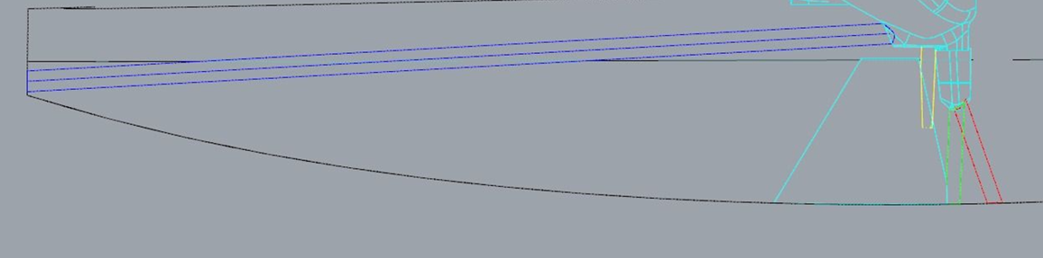
I am seeking clarification regarding the legality of adding a drainage system for the mast well on an IOM hull. Please refer to the attached diagram illustrating several possible solutions. Could you please advise which of the following options are permitted under the current IOM Class Rules?
- [Question 1A] Red: Connect a drain pipe from the mast well:
(a) Directly down through the bottom of the hull (below the waterline).
(b) Through the hull side above the waterline (instead of below).
- [Question 1B] Green: Connect the mast well drain to the fin trunk, enlarging the existing hole for the fin box to allow water to pass through.
- [Question 1C] Yellow: Connect the mast well drain to the fin trunk without modifying the fin hole, relying on a slight gap between the fin and fin box for water to exit.
- [Question 1D] Blue: Route the mast well drain aft to the transom, exiting at the stern.
- [Question 2] Relying on a slight gap (how large a gap would still be considered acceptable) between the fin bolt and the fin box, and between the fin and the fin box, for water to exit.
I kindly request your guidance on whether these drainage solutions comply with the Class Rules.
Thank you very much for your time and clarification.
Zvonko Jelacic
Received from designer & builder Ernst Rohner.
Questions:
[…] I have questions concerning the topic “draining the mast/cockpit well by the keel box or by the keel sides”. Thank you very much for your clarifications and rule guidance.
Please find below a couple of pictures that exhibit the situation and the 3 design approaches.
[Question 3A] Approach 1: Semi-circular draining channels on both sides of the keel box only, with semi-circular channels being part of the keel trunking in the hull.
[Question 3B] Approach 2: Semi-circular draining channels on both sides of the keel head only, without semi-circular channels being part of the keel trunking in the hull. The keel trunking in the hull follows the smooth shape of the keel profile.
[Question 4] Are 2 additional holes in the mast/cockpit well IOM class rule compliant?
Which of these approaches are IOM class rule compliant, if any?
Picture 1 [Question 3A]:
Keel box with draining channels and keel trunking including draining channels.

Picture 2: [Question 3B]
Keel head with draining channels

Picture 3 [Question 4]:
Two openings/ holes in mast well

Answer:
Relevant IOM class rules
Introduction
The class rules for the International One Metre Class are closed class rules in which anything not specifically permitted by the class rules is prohibited. Individual rules may require, limit, or permit as necessary.
D.2.2 CONSTRUCTION
Construction is unrestricted subject for the following:
(b) Except for trunking for the keel and rudder, the hull shall not have:
(1) Voids in the waterplane and/or the underwater profile.
- Hollows in the plan view that exceed 3 mm,
- Hollows in the underwater profile that exceed 3 mm,
E.3.2 [KEEL AND RUDDER] CONSTRUCTION
Construction is unrestricted subject to the following:
- The keel and rudder shall not
(3) have openings through which water could flow when in use.
Relevant Terminology:
A void in the context of the hull’s waterplane or underwater profile refers to a closed shape that is inside the closed shape defined by the waterplane or underwater profile – i.e. it is a hole in the 2D surface defined by either the waterplane or the underwater profile.
A hollow in either the hull’s underwater profile or plan view is a concavity in a line that defines those views.
Trunking is not a defined term in the RRS, ERS, or IOM Class Rules. In this context, its meaning is broadly an enclosure or casing in the hull for the rudder or keel.
Answers to questions:
[Question 1A] Red: Connect a drainpipe from the mast well:
(a) Directly down through the bottom of the hull (below the waterline).
Answer: Not permitted due to the void in the waterplane caused by the drainpipe (IOM Class Rule D.2.2(b)(1))
(b) Through the hull side above the waterline (instead of below).
Answer: Permitted.
[Question 1B] Green: Connect the mast well drain to the fin trunk, enlarging the existing hole for the fin box to allow water to pass through.
Answer: Permitted
[Question 1C] Yellow: Connect the mast well drain to the fin trunk without modifying the fin hole, relying on a slight gap between the fin and fin box for water to exit.
Answer: Permitted. This relies on the exit of the drain being above the waterplane otherwise it will be a void in the waterplane and, therefore,not permitted.
[Question 1D] Blue: Route the mast well drain aft to the transom, exiting at the stern.
Answer: Permitted provided the exit point is above the waterplane. If the exit is below the waterplane, a void in waterplane is created and, therefore, it is not permitted.
[Question 2] Relying on a slight gap (how large a gap would still be considered acceptable) between the fin bolt and the fin box, and between the fin and the fin box, for water to exit.
Answer: Permitted.
[Question 3A] Draining channels on either side of the fin box/trunking.
Answer: Permitted – there is no restriction on the shape of the trunking for the keel.
[Question 3B]. Draining channels in the head of the keel fin.
Answer: Permitted. Although the channels in the keel fin are “openings”, provided they are completely contained within the trunking, water cannot flow through them. As a result, Rule E.3.2(b)(3) is not triggered.
[Question 4]. Holes in the bottom of the mast well leading directly to the keel trunking.
Answer: Permitted (same as Question 1C).
Is an interpretation and consequent Class Rule change needed?
No.
IOM ICA Technical Subcommittee
Andrew Crocker, VC Technical
Robert Grubiša, member
David Jensen, member
Updated February 2026
Which of arrangements shown on the sketches below are permitted according to the IOM Class Rules?
A – Second fastening would protrude through hole in hull.
B – Single fastening only
C – Variation on trunk. Single void for keel trunk
D – Same as C with 2nd fastener


Relevant IOM Class Rules:


Answers:
Ver. A: Not permitted because the 2nd fastening (as a part of the hull) extends more than 60 mm below the waterline (IOM Class Rule C.4.1)
Ver. B: OK
Ver. C: OK
Ver. D: OK
Is an interpretation and consequent Class Rule change needed?
No.
In the IOM class Is it permissible to build a rudder with one or more (approximately) horizontal foils on the (approximately) vertical blade? Is it permissible to build a rudder on a single shaft that has more than one blade, each inclined at a different angle to the central vertical plane?
Is a "belt drive sheet control line/unit" permitted to be used on an IOM class boat?
Is it permitted to use headsail swivel made of a cord attached inside the watertight tube connecting bottom of the hull and deck and passing through the tube up to the deck level where it is attached to the headsail boom?
Are the U-shaped nails driven into a wooden mast as attachments for the mainsail luff to the mast in accordance with IOM Class Rules?
Is it permitted to tension a jackstay/luffline of an IOM mast enough to hold a pre-bent mast straight?
Questions related to the various mainsail boom kicking strap arrangements
Questions details:
Which of the following rig arrangements are permitted?
Case 1:The kicking strap is not adjustable and is fixed at each end. The forward end of the main boom is moved (up & down or fore & aft) using a fitting that is:
a) combined with the gooseneck fitting or
b)in addition to the gooseneck fitting

Case 2: The kicking strap passes through the boom and is adjusted in a fore & aft direction at the aft end of the main boom by using a fitting that is:b) in addition to the gooseneck fitting.
a) combined with the clew fitting or
b) in addition to the clew

Case 3: The kicking strap is not adjustable and is fixed at each end. The forward end of the boom is not adjustable on the gooseneck in any direction except for rotation. The clew of the mainsail is adjustable vertically by using a line that is:
- a) combined with the clew fitting or
- b) in addition to the clew

Case 4: The kicking strap is not adjustable and is fixed at each end. The forward end of the boom is not adjustable on the gooseneck in any direction except for rotation. The rotational axis of the gooseneck is adjustable by:
- a) rotation or
- b) in vertical position with respect to the mast.

Case 5: As case 1 except that the kicking strap is adjustable.
Case 6: As case 3 except that the kicking strap is adjustable.
Case 7: As case 4 except that the kicking strap is adjustable.
Reference to the old interpretation issued before year 2017
Interpretation 2012- IOM-1 on the IOM CR – edition 2011
Answers:
In all answers it is assumed that kicking strap, as part of running rigging, is capable to work in tension only.
Case 1(a)
The IOM Class Rules do not specifically permit a special fitting to adjust the forward end of the boom up and down, or fore and aft. This arrangement is therefore prohibited. IOM Class Rule F.2.4(b) however permits the gooseneck to be adjusted and there are no restrictions as to the directions.
Case 1(b)
The IOM Class Rules do not specifically permit such an “additional fitting”. This arrangement is therefore prohibited.
Case 2(a)
IOM Class Rule F.4.3(a)(3) requires a kicking strap fitting, IOM Class Rule F.4.3(a)(1) requires mainsail clew fitting(s) and IOM Class Rule F.2.4(a) allows fittings to be combined. This arrangement is therefore permitted.
Case 2(b)
IOM Class Rule F.4.3(a)(3) requires a kicking strap fitting. This arrangement is therefore permitted.
Case 3(a)
IOM Class Rule F.4.3(a)(1) require mainsail clew fitting(s), IOM Class Rule F.6.2(b)(2) permits a mainsail clew line and IOM Class Rule F.2.4(a) permits fittings and control lines to be combined. This arrangement is therefore permitted.
Case 3(b)
IOM Class Rule F.4.3(a)(1) require mainsail clew fitting(s) and IOM Class Rule F.6.2(b)(2) permits a mainsail clew line. This arrangement is therefore permitted.
Case 4(a)
IOM Class Rule F.2.4(b) permits fittings to be adjusted and there are no restrictions as to the directions. This arrangement is therefore permitted.
Case 4(b)
IOM Class Rule F.2.4(b) permits fittings to be adjusted and there are no restrictions as to the directions. This arrangement is therefore permitted.
Case 5
IOM Class Rule F.2.4(b) permits an adjustable kicking strap. The Case 1 interpretations apply to the “additional fitting”.
Case 6
IOM Class Rule F.2.4(b) permits an adjustable kicking strap. The Case 3 interpretations apply to the boom fitting(s) and the line.
Case 7
IOM Class Rule F.2.4(b) permits an adjustable kicking strap.
Questions related to the various headsail boom topping lift restraint line(s) arrangements
Questions details:
Are devices in following examples permitted?
Question 1
A device of type 1 is shown in Diagram1 being a loop which may be attached to the topping lift and/or the headsail stay.
Alternatively it may be a loop formed in the topping lift itself when the latter is made from cord, when it may be considered part of the topping lift.

Question 2
Diagram 2 shows an elastic line of type 2 which tensions the topping lift when the boom rises in a gust.
At one end it is attached to the topping lift and at the other is attached to the boom or a fitting on the boom.
A variation has it attached to the topping lift, passing through an eye on the end of the boom then passing forward to be attached to the boom as shown by the dotted line.

Question 3
Diagram 3 shows a basic topping lift extended by a loop of cord which passes through an eye on the end of the boom and a further extension by an elastic line which is attached to the boom.
A ball on the end of the loop permits the topping lift to raise the boom as required, while the elastic line pulls the loop through the eye to take up the slack in a gust.

Question 4
Diagram 4 shows a loop attached to the headsail and passing around the topping lift.
A variation has the loop passing around the headsail and attached to the topping lift.
Both are of type 2

Question 5
Is it permitted to have any combination of two or more of the various types of line shown in diagrams 1 to 4 ?
Reference to the old interpretation issued before year 2017
Emergency IOM Class Rule changes made after Interpretation 2014-IOM-3 on IOM Class Rules 2013 has been published
Answers:
All presented devices/arrangements are permitted by the IOM Class Rules F6.2(b)(8) which permit use of one or more headsail boom topping lift restraint lines. IOM Class Rule C.7.6(c) describe the way of attachment and passing around other parts of rig and headsail.
Question:
Is the size of the rotating part of the mainsail halyard fitting listed in the IOM Class rule F.3.3(c)(1) limited in any way?
Question details:
Is the size of the rotating part of the mainsail halyard fitting listed in the IOM Class rule F.3.3(c)(1) limited in any way?
Reference to the old interpretation issued before year 2017
Interpretation 2003-IOM-4 on the IOM CR – edition 2002
Answer:
IOM class rules F.2.3 and F.2.4 (a) restricts the size of the fittings.
Is it permitted to fit a boat with more than one ‘sheet control line’? Is it permitted to work the mainsail sheet and headsail sheet with more than one sheet control line?
Questions related to the various shroud attachment points on the mast
A strut normally works in compression so is one that acts in tension compliant with IOM class rule F3.3(b)(9)?
Questions related to the headsail boom swivel arrangements.
Is it permitted to use stainless steel rigging (including steel mast spar jackstay) as stated in the IOM class rule F.5.1 having in mind ERS defined term rigging?
Questions related to the headsail and mainsail sheets materials and arrangement
ERS 2017-2020
IOM CR 2018
Is it permitted to have the forestay and headsail halyard both connected to the ring of a swivel hook made as shown in the graphic below?
Question details:
Is it permitted to have the forestay and headsail halyard both connected to the ring of a swivel hook made as shown in the graphic below?

Figure 1
Is it permitted to have any types of standalone swivels (with or without ball bearings) in the forestay?


Figure 2 Figure 3 Figure 4
Answer:
Relevant IOM class rules


Relevant Equipment Rules of Sailing rules:
Discussion:
A termination is a way of attaching a piece rigging (standing or running, line or wire) to a spar (mast, boom) or the hull. Length and tension adjustments are specifically permitted by the class rules F.5.3 and F.6.3.
In addition, the position of parts may be adjustable by class rule F.2.4(b).
Rotation/swivelling is not specifically permitted for terminations.
It is allowed to have more than one part in terminations. Terms in F.5.3 and F.6.3 are plural. A few examples are:
- Rigging screw is a permitted length and tension adjustment combined with a termination.
- A hook fixed to a length of rigging using a crimp covered with heat shrink material.
Figures 3 and 4 are showing multi parts terminations but one of the parts is a fishing swivel so they are not allowed.
Answers:
- Items on Figures 1 to 4 are not permitted.
Is an interpretation and consequent Class Rule change needed?
No.
Is it permitted to have dents instead holes in the mast spar on fixing positions of above mentioned fittings?
Is controlling of the fixed length kicking strap tension using screw in the main boom, a knurled nut and a slug that connects via a rod to the kicking strap strop that attaches to both sides of the boom permitted?
Control of the fixed length kicking strap tension screw in the main boom
Received from Colin Hatton – designer and builder via GBR NCA
Question:
Is controlling of the fixed length kicking strap tension using screw in the main boom, a knurled nut and a slug that connects via a rod to the kicking strap strop that attaches to both sides of the boom permitted?


Answer:
Arrangement shown on the photo is considered as a kicking strap fitting with adjustable position to allow the functioning of the fixed length kicking strap.
The fitting should be no bigger than needed for its purpose meaning that the screw/threaded rod in the main boom should be such to allow the movement of the nut for control of the mainsail leech and not to provide additional stiffness to the main boom.
The class rules do not provide for reinforcement of the boom spars in way of fittings.
Having in mind arrangement shown on the sketch and the above mentioned restriction, such kicking strap fitting is permitted.
4 February 2025
Is headsail boom swivel fitting as shown in sketch in accordance with the IOM Class Rules?
Q&A – headsail boom swivel fitting
Received from Graham Bantock – IOM designer and builder
Question:
Is headsail boom swivel fitting as shown in sketch in accordance with the IOM Class Rules?


Answer:
Boom spar may have openings for fitting and rigging. Class rules are not defining the size of such opening. Headsail boom mandatory items are swivel and/or its fittings.
The size of the fitting shall be limited to what is normally provided by items of their type.
This type of fitting is permitted.
Is controlling of the fixed length kicking strap tension using set of lines and attachment points on a main boom as shown on photo below permitted?
Control of the kicking strap tension using a main boom fitting(s)Received from Colin Hatton – designer and builder via GBR NCAQuestion:Is controlling of the fixed length kicking strap tension using set of lines and attachment points on a main boom as shown on photo below permitted?
Relevant IOM Class Rules (2026 Revision)
F.4.3 MAINSAIL BOOM FITTINGS
(a) MANDATORY
(3) Vang fitting(s).
(b) OPTIONAL
- Opening(s) for mainsail boom sheet and/or vang fitting(s).
Answer
It is assumed that the lines shown on the photo are used to control tension of the fixed length kicking strap below the part of the deck. There are more than one kicking strap fitting, marked with red arrows:

Class Rule F.4.3. now permits multiple vang fittings on the boom, so the arrangement depicted above is permitted.
Is an interpretation and consequent Class Rule change needed?
No.
Revised: February 2026
First Issued: March 2025
Can vangs operate in compression?
Do the IOM Class Rules limit the size of a vang?
Is it permitted to use metal eyelets for openings on the mainsail luff? Is there a restriction on the location of any of these eyelets?
How shall a seam be checked for compliance with class rules G.3.2(a)(1) or G.4.2(a)(1)?
Are the sail panels made of two different ply – translucent and the same one with white pigment added in compliance with G.3.1(a)(2) and G.4.1(a)(2)?
Question details:
The sails shown in the photo were submitted for measurement.
The manufacturer of these sails considers that all the sail panels are of the same ply and the white panels are the same ply with pigment added.
An interpretation or explanation of G.3.1(a)(2) and G.4.1(a)(2) with respect to these sails is requested.

Answer:
According to the ERS G.1.4 (b) Ply is a sheet of sail material.
According to the IOM Class Rules G.3.1(a)(2) and G.4.1(a)(2) the body of the sail shall consist of the same ply throughout.
So, a same sheet of sail material must be used for the construction of an IOM sail. The sail material from the same roll/batch shall be used for a construction of a sail. Sails on photo attached to the request for interpretation/explanation are made of two different ply. Sail panels made of ply of different colours, weight, surface finish and pattern are not the “same ply” as requested by the IOM Class Rules G.3.1(a)(2) and G.4.1(a)(2) and therefore not permitted.